10+ er diagram 1 to many
When the first-ever geographical map which is now known as Atlas was drawn. Follow these instructions to learn how to use er diagram symbols and easily create more er diagram symbols with EdrawMax.

Progress Monitoring Tracking Sheet How To Make A Progress Monitoring Tracking Shee Social Media Strategy Template Progress Monitoring Study Schedule Template
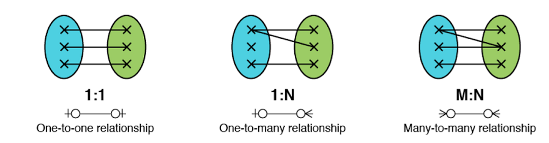
Many-to-Many Cardinality- By this cardinality constraint An entity in set A can be associated with any number zero or more of entities in set B.

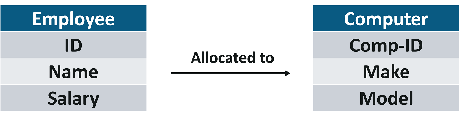
. And a relational model will have an extra table often called a junction table between two entity tables that are linked by a many-to-many relationship. You may preferably keep the same name for the entity or give it a. To export in a vector format use To PDF File instead.
Each link is supposed to take me to the brief explanation and example but numbers 7 10 and 14 dont work. Example In this ER diagram both entities customer and driving license having an arrow which means the entity Customer is participating in the relation has a in a one-to-one fashion. EdrawMax is well equipped to design a er diagram.
Why do plant cells possess large-sized vacuoles. In ER diagram key attribute is represented by an oval with underlying lines. One to one relationship11.
Entities and Simple Attributes. This allows for simplified editing using Inkscape or other vector image editor. Dbdiagramio A web-based ER diagram tool that enables design sharing.
Mind Mapping ER Diagram DFD Flowchart CRUD Traceability Map Requirement Diagram and Requirement table. In another type of notation one dash is added to the relationship line at both ends. At the zero-pressure limit the compressibility reaches a minimum of 44 10 10 Pa 1 around 45 C before increasing again with increasing temperature.
This is where ER modeling comes in. The diagram is exported. Later the same concept was used to draw the maps of stars and constellations.
Hi i am student of bca 6th sem. CS3200 Database Design Spring 2018 Derbinsky Outline 1. The idea of schematic diagrams came into existence somewhere in 1300 AD.
2020-10-01 410 Yes Core tool. I cant draw ER diagram for my project websitein my project i have 4 database tables so how i creat ER diagram 14032014 - reply. Entity-Relationship ER Diagrams Lecture 7 February 11 2018 Entity-Relationship ER Diagrams 1.
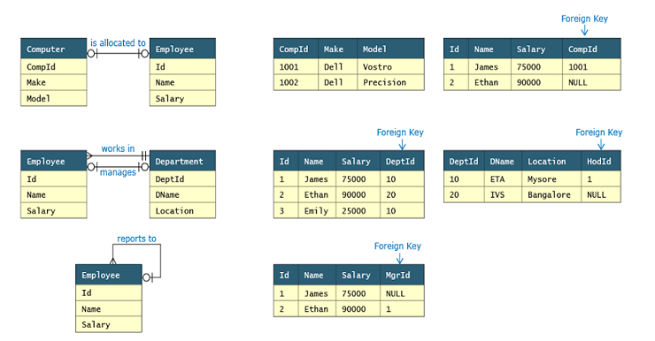
An entity type within ER diagram is turned into a table. These instructions may work for SQL Developer 320923 to. As time passed the structure of the schematic diagrams modified and somewhere in the 20th century leaving behind the.
One course can be enrolled by any number zero or more of students. Input or export can be by diagram or Umple textual form separation of concerns aspects traits mixins embeds action code in Java and other. A one-to-many relationship is represented by adding 1 near the entity at left hand side of relation and N is written near the entity at.
41 How to Use ER Diagram Symbols in EdrawMax Instead of wasting time drawing the er diagram symbols or icons on paper you should look for a way to design a er diagram easily. In ER diagram attribute is represented by an oval. It is represented using an arrowThere can be many notations possible for the ER diagram.
Entity-relationship diagrams or ERDs provide a visual way to understand the relationship between entities which in other words a container of information. How to make a model of a plant cell diagram step by step procedure. Thus weve put together a list of free ER diagram tools that will help you construct a relational and logical structure of a database.
ER Diagrams are most often used to design or debug relational databases in the fields of software engineering business information systems education and research. A relational model has the foreign keys included in the tables and these serve to implement the relationships which the ER model identifies. The ER diagram will extend over many pages and that means you will need to generate views of different areas and also get a tool that enables you to scroll around a much larger design area.
Provides API and Plugins RTF HTML Export. The ER diagram represents the conceptual level of database design meanwhile the relational schema is the logical level for the database design. This junction table contains two or more foreign.
A one-to-one relationship is represented by adding 1 near the entities on the line joining the relation. We will be following the simple rules. The bulk modulus of water is about 22 GPa.
Vacuole functions in the storage of substances maintenance of osmolarity and sustaining turgor pressure. I did notice that a few of your shortcut links up top are broken. Number 13 actually takes me to the location for number 14.
As the pressure is increased the compressibility decreases being 39 10 10 Pa 1 at 0 C and 100 megapascals 1000 bar. Near the very beginning of your UML diagram types page you provide a numbered list of diagram types. It is available in free and paid versions.
Consider the following ER diagram- Here One student can enroll in at most one course. Browse to and select the export file location. Click File Data Modeler Print Diagram To Image File.
The plant cell diagram can be checked above and on a similar pattern the diagram can be created. Key Attribute The attribute which uniquely identifies each entity in the entity set is called key attributeFor example Roll_No will be unique for each student. An Entity Relationship ER Diagram is a type of flowchart that illustrates how entities such as people objects or concepts relate to each other within a system.

Introduction To Er Diagram Model Knoldus Blogs

Msnkhan I Will Do Database Schema Design And Normalization For 10 On Fiverr Com Database Design Sample Resume Relational Database

Introducing Modern House Plan In 30 X 50 By Er Sameer Khan Contact For More Details 30x50 House Plans 20x40 House Plans My House Plans
10 Erd I E Entity Relationship Diagrams Interview Q As Java Big Data Career Companion
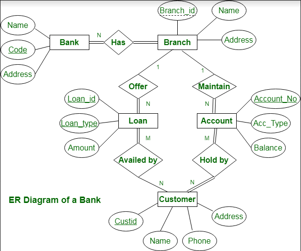
Er Diagram Of Bank Management System Geeksforgeeks
What Is An Er Diagram And How To Implement It Edureka

The Loudon Sl 2054 House Plan By Bridgewater Architectural Design For Southern Living Artfoodhome Co Southern Living House Plans New House Plans House Plans

Causal Event Tree Tree Diagram Statistical Methods Probability

Dbms Case Study Dbms Erd Management Information Systems

Circuit Diagram Of A Torch Circuit Diagram Diagram Electrical Diagram

What Is An Er Diagram And How To Implement It Edureka
What Is An Er Diagram And How To Implement It Edureka
What Is An Er Diagram And How To Implement It Edureka

Invoice Data Model Erd Database Design Data Modeling Business Architecture

Pin By Ora Designers On My Views House Floor Plans House Layout Plans Beautiful House Plans

You Can Try The New Version With An Entirely Complimentary 30 Day Trial The Low Tech Version Emp Budget Planner Template Spreadsheet Template Planner Template

10 Process Infographic Templates And Visualization Tips Customer Journey Mapping Design Thinking Process Journey Mapping